Fuel Gauge Ohm Rating
Traction Owner’s Club › Forums › Technical › Electrics › Fuel Gauge Ohm Rating
- This topic has 8 replies, 4 voices, and was last updated 4 years, 1 month ago by Roger Grix.
-
AuthorPosts
-
26th February 2020 at 1:58 pm #26208
189
ParticipantAnyone know the ohm rating for the Jaeger fuel gauge fitted to the 52 Light 15?
I decided to replace the non-original tank sender unit with one from Moss Europe that was described as for the Jaeger gauge and looked like the original,
but I wonder whether the sender unit and fuel ohm ranges match.
David Wood
26th February 2020 at 3:11 pm #26209David Faulkner
ParticipantFloating Power Vol 27 2003 issue 5 has an item on overhauling the sender unit and gives the resistance as 110-120 ohms – look in members area for it: https://traction-owners.co.uk/wp-content/uploads/2017/03/Floating-Power-Vol-27-No-5-Aug-2003.pdf
26th February 2020 at 7:07 pm #26211Alistair
ParticipantWhy not measure the resistance of the sender full and empty?
Alistair
28th February 2020 at 3:30 pm #26215ParticipantThanks for your help. I’ll download the article and see how I get on. Digital multimeters tend to give erratic resistance readings when moving the arm though.
29th February 2020 at 10:45 am #26217Roger Grix
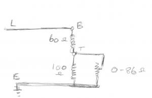
ParticipantI am not sure if the ’52 is the same as the ’55 but for my ’55 L15, the gauge resistance between B and T is 60 ohms, between T and earth (case) is 100 ohms. The sender varies between 0 and 86 ohms. If the sender is erratic, open it up and clean the sliding contact.and the coiled wire.
When the tank is full it should read high and, when empty, it should read about zero.
Also, make sure that you have an effective earth on the sender. Don’t rely on connecting it to the tank.
29th February 2020 at 4:01 pm #26218ParticipantThis is turning out to be more confusing than I expected. The resistance at the gauge between B and T terminals is 60 ohms and T and earth is 100 0hms as you specify and the new sender unit does have a range from 0 – 84 ohms. However the gauge seems to need inputs of between 0 – 190 ohms to register from empty to full, because the new sender at maximum extension shows no more than a quarter full. So something is amiss.
1st March 2020 at 5:29 pm #26220ParticipantCan you post a picture of the back of your gauge?
I am guessing that the basics are the same as my one, even if the shapes are different.
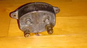
You will see the two nuts for the wires and the other two nuts on studs in slots. This allows the coils to be move closer to or further from the needle armature to give each coil a variable effect on the needle movement. These studs adjust the positions of the 2 internal coils.
The following is what I did with mine and it’s not too bad. I’d suggest taking everything out of the car and putting the bits on the workbench. Connect up the bits. Join the body of the meter to the body of the sender (the earth connections).
Connect 12V between the B terminal and the earth (body). With the sender in the empty (down) position, the T coil is basically bypassed by the sender which is approximately zero ohms.
Adjust the B coil to give you “Empty”. Moving the coil in increases its effect and out reduces it.
Now lift the sender to the full position and adjust the T coil to give “Full”. The two coils will probably interact with each other a bit and will require a bit of fiddling back and forth.
Beware of the problem that I had. I fiddled for ages trying to get zero before I realised that the needle was bent – mechanical problem, not electrical J.
I hope that this helps.
R
5th March 2020 at 2:37 pm #26228ParticipantDear Roger
Thanks to your advice I was able to match the sender to the fuel gauge readings. So the gauge is working as it should and for the first time in years I’ll have a good idea of how much petrol’s in the tank.
You’re a hero!
David
6th March 2020 at 5:41 pm #26233ParticipantGlad to have helped.
R
-
AuthorPosts
- You must be logged in to reply to this topic.